
Let’s clear one thing first. This is not a “Step by step -How to” guide to make your own variable isolation transformer. This is just me sharing my work, comments and ideas while building a piece of much needed equipment for my bench. Maybe it gives you a little push or sparks an idea for doing something similar.
Whether you are diagnosing a broken piece of electrical equipment or testing a repaired one, there comes a moment when you have to plug it into mains. That moment is like playing a lottery. Everything could work out great or it could go BOOM and trip your apartments fuse. Not once did I repair something and only way to test it was plugging it to mains and hoping for the best. Lots of times everything worked out great, but other times, one missed component caused even worse problem and destroying all the new parts.
Tripping the fuse could be avoided by a simple isolation transformer. But why stop with a simple solution when you can complicate your life and spend your time and money on something more versatile.
Variable isolation transformers exist as a commercial unit. One of the more interesting is models is: Sencore PR570
But… there were three big obstacles stopping me from buying a commercial unit:
1. General unavailability in my country
2. Total cost (unit, transport and import taxes)
3. Physical size
Last obstacle was the biggest problem of all (pun intended). Since my work area is very limited so is my bench space. And I just couldn’t find any product that would fit my small desk. So, I decided to build my own. Device, not a desk 😊.
Every component used in a design of this VIT (Variable Isolation Transformer) was a compromise between the physical size of the unit and usability in everyday work.
Biggest supplier of electronic components in my general area is: www.tme.eu . They are not as big as Digikey or Mauser, but they are good enough. And my only financially viable choice.
That is the reason why most of the components used to build this project is linked to their web site. Availability of the certain items like DIY plastic cases and variacs also had a major impact on the final product.
After some time of planning and deciding what I want of the final product, these were my main goals:
- It must fit on my bench
- It must isolate DUT (Device Under Test) from mains
- It must regulate output voltage from cca. 1 – 110%
- It must show main parameters like voltage, current, power, power factor
- It must be safe for the operator and DUT
- It must have current limit regulation
- It must be able to fit multitude of electrical plugs
- It must allow me to choose different modes of operation
Taking all the above in consideration, this was the general idea of the block diagram:

There were two options for the user interface of the device. Buttons with latching mechanism connected directly to its dedicated relay, or processor-controlled environment with momentary switches and more flexible control of the whole unit.
I chose the latter. It complicates things quite a bit but adds a certain degree of flexibility and fine tuning of the final product.
Since I am not an advanced programmer (easily seen as soon as you go through my code) I opted for Arduino Uno R3 clone: Keyestudio UNO R3
After few revisions this is my final schematic for the user interface of the VIT:

Let’s clear some things before we go deeper into hardware details.
I am by no means an electronic PCB designer. And as I said before, I am far, far from coding expert too.
That said, all my builds and devices are based on electronic modules and PCB-s that I am able to source from web shops like eBay, AliExpress, etc. All I do is try to integrate and interconnect simple modules to form my idea of the final product. Now that we’ve cleared that, lets dive into component selection and final product build.
Product components choice:
After measuring my available desk space and checking all available components, I decided to go with:
Z39W KRADEX Enclosure with panel. Dimensions: 294 x 217 x 120mm (11.57 x 8.54 x 4.72in)

Choice for the variac that would fit this case boiled down to:
Variable autotransformer OIEA3 BREVE TUFVASSONS: link
| Primary voltage 230V AC Output voltage 0…260V IP rating IP00 Thermal class Ta40B Ccurrent 2.8A Weight 3.3kg |  |
Isolation transformer was custom made in small local business:

Power: 600VA
Dimensions: 137 x 59mm
Weight: 3,9kg
POWER METER
After deciding on three main components, I needed a good power meter. It had to be independently powered, capable of 0 – 300V measurement and it had to have a good resolution in 0-5A current range.
And believe me when I say, it was hard to find one that would roughly fit the purpose. I bought several devices. Some were not sensitive enough; some didn’t work on independent power source and some had an extremely bad LCD visibility angle. Finally, I settled for one that was a good compromise that suited my purpose: 6 in 1 Combo Voltmeter Peacefair: PZEM-018, that can be found on eBay or AliExpress for 7 – 10€
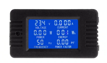
This power meter, same as most of others, uses the voltage it measures as a mean to power itself.
That is not something that works for me because it has input range from 80 – 300V. Under 70V it turns off. For that reason, I had to do some modification. I opened the instrument and disconnected its inbuilt power supply of 5V by removing its rectifier diode. Instead, I soldered 1117-5V LDO, since my main power supply for whole VIT is 12V. This way, power meter was independently powered by external power supply. That enabled it to measure full range from 0 – 300V without shutting off.

Front View 
Back View 
Internal – removed diode 
Internal – removed diode 
Added 1117-5V 
Added 1117-5V 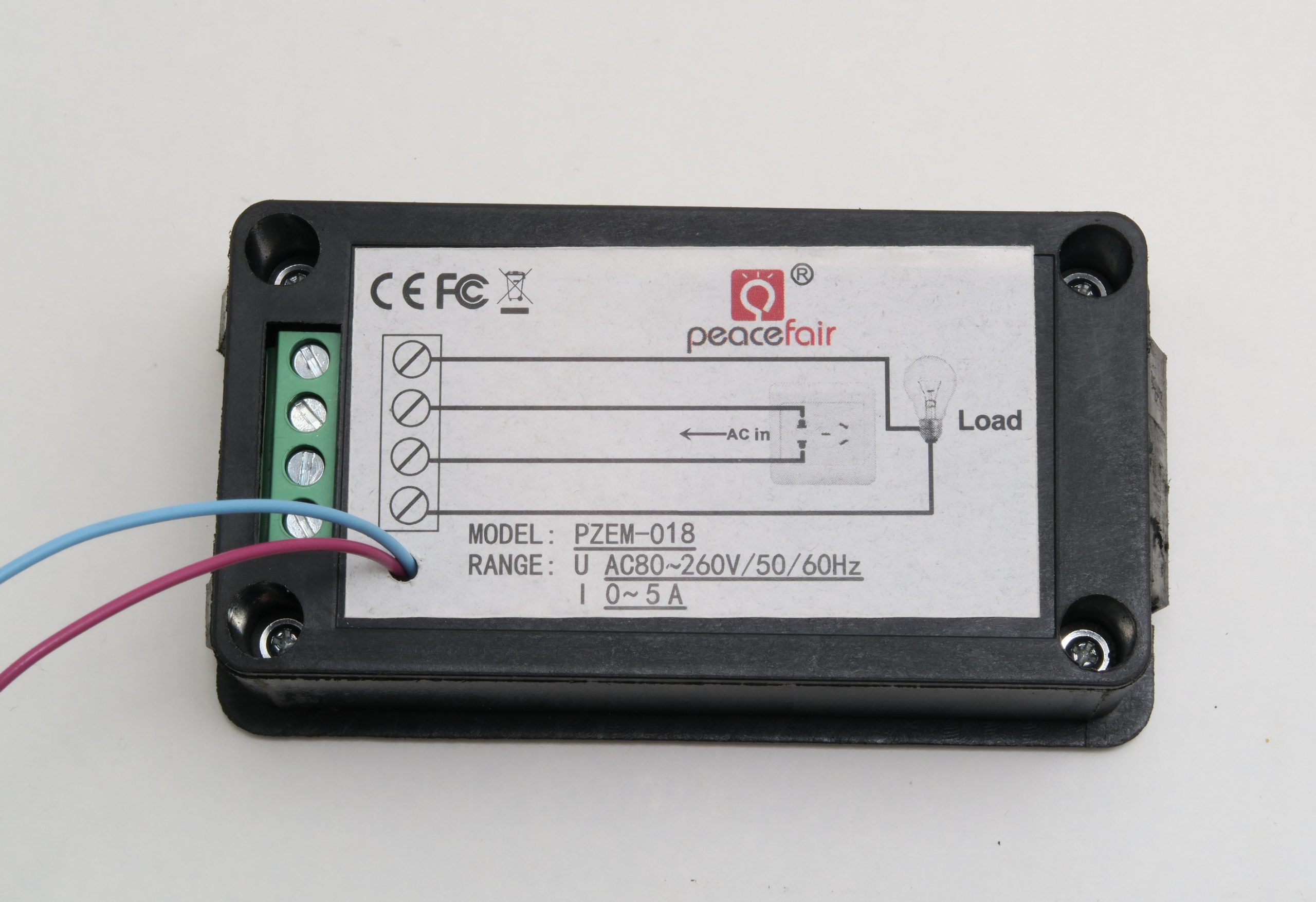
Adapted to external PSU
After settling for the fourth major component, I could now come closer to my final design. To give you some perspective, this is how I planned the positioning of internal components inside of device:
How I planned dimensions and clearance of the components:

Components Layout Plan 
Interface Panel ideas


Relay Control
Next in line was finding a solution for relay control and connection to the Arduino controller.
As I mentioned before, I am not very skilled in designing PCB-s and currently don’t really have any time to invest in learning it. That is where products from AliExpress come to rescue.
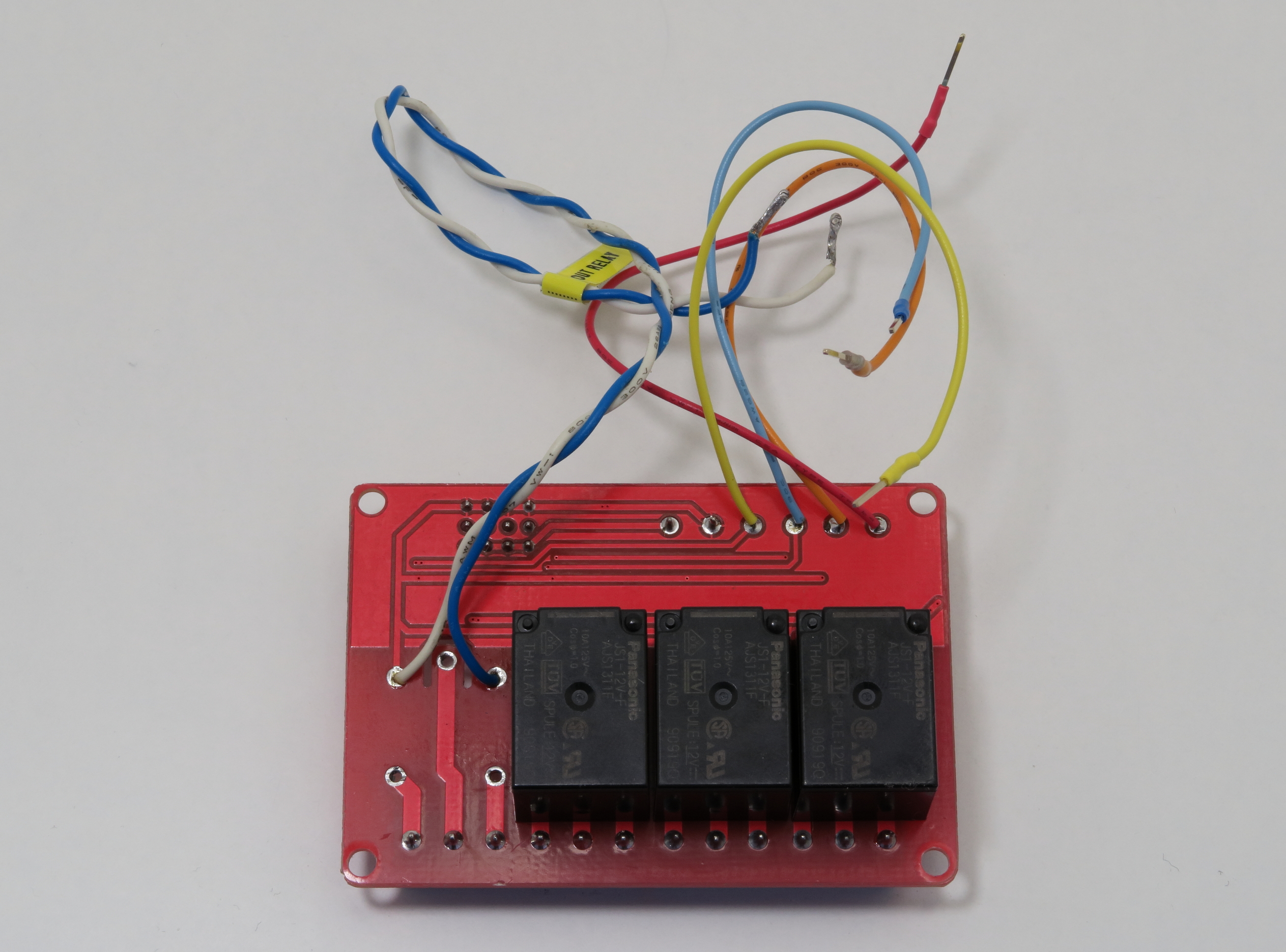
I bought a 12V-four channel Arduino relay board for 2.5€ total. The most important thing was a complete solution with easy Arduino connectivity, optocoupler protection and flexible configuration.
For 2.5€ in total you can’t expect to get some high-quality relays. And since I need this device to be quite reliable, I decided to buy some quality relays from Panasonic.

Panasonic relays were physically bigger than original ones, so I needed to be creative. Original relays were de-soldered and Panasonic relays were soldered from the bottom side which had more than enough space.
Output relay was the main connect – disconnect device so I opted for WEIDMÜLLER 7760056050 with corresponding socket:

Current Limit
For the current limit solution another AliExpress board was used: “AC Current Detection Sensor Module 5V 12V 24V”

I bought a 5V board, but later in design I opted for 12V power supply. And instead of waiting another month for a 12V board, I reviewed all the pictures from AliExpress and figured out that only difference is the relay itself (5 or 12V). All other components were exactly same.
First revision of the design used the inbuilt relay for disconnecting the circuit if overcurrent event occurred, but later I changed it to processor (Arduino) controlled interrupt event and ditched the relay. To do that, board needed to be adapted a bit. Relay was removed, pullup resistor added, and a sensor wire routed to Arduino interrupt input.

Current Limit Board Front 
Current Limit Board Back
Also, the trimmer resistor was removed from the PCB and extension wires were added so that a potentiometer could be used on the front panel. Screw terminals on the current sensor board were used as a distribution contacts for 12V power supply.
Cooling solution
As a cooling solution I used an old Antec 3 speed 12V fan I had laying around from some old computer case.

Brain Board
For the brain of the device, I chose Arduino Uno R3 clone: Keyestudio UNO R3 since it can be powered directly by 12V

Power supply
Front panel components:

Assembly
Now that we have most of the components covered, lets get on with assembly
Main issue of VIT is its weight. Isolation transformer + variac contribute to 80% of its weight which is substantial 8kg.
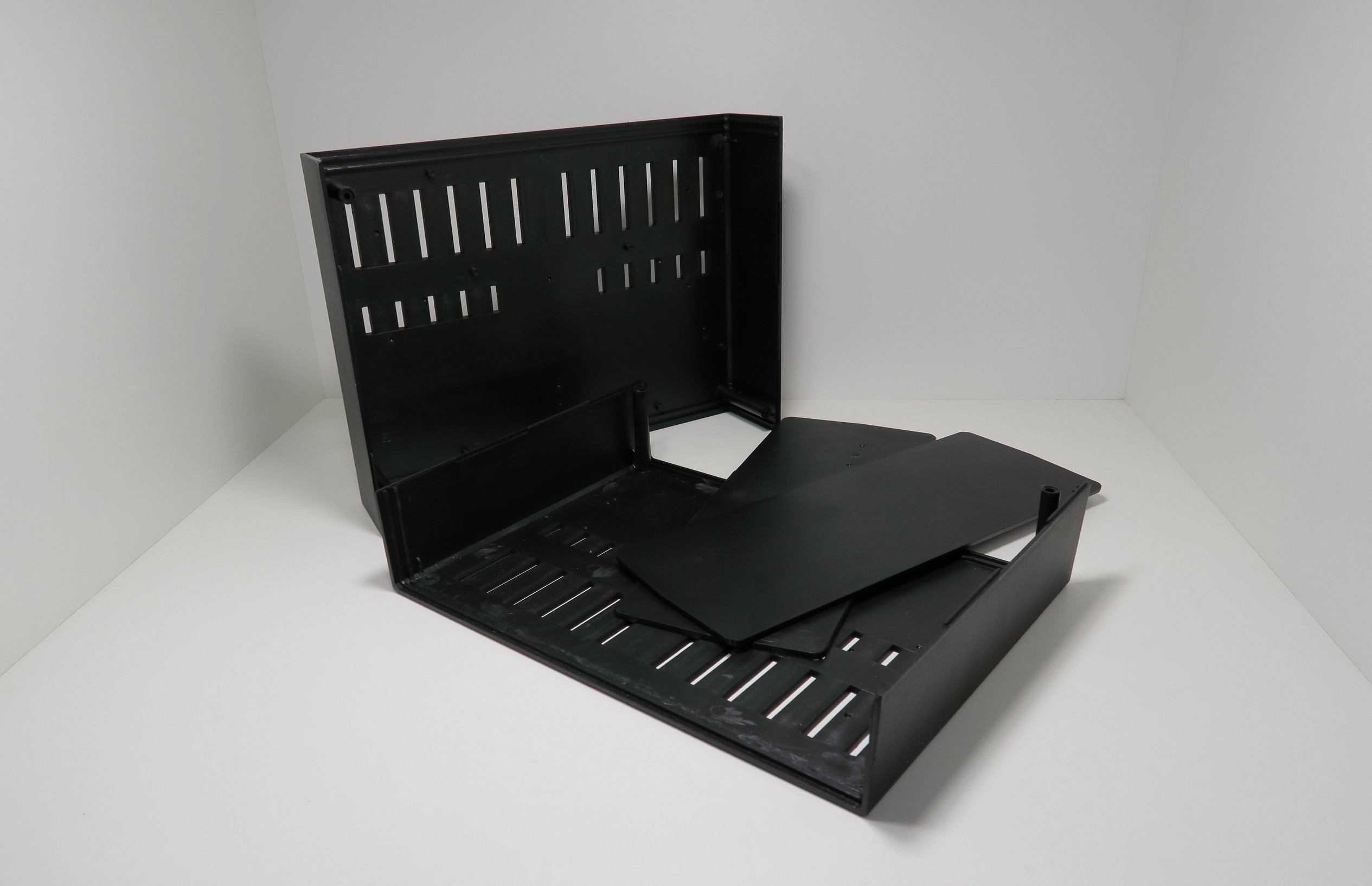
Plastic case can’t handle that weight without deforming so a solution was needed for adding some structural integrity. I stumbled on a piece of aluminium case from and old spectrophotometer. It was a 2mm aluminium piece with a 90° bend in it. So, I measured and cut out a piece that best suited my purpose.


I live in an apartment and have a limited number of tools. Everything you see was done either in my room or on the balcony with basic electric and lot of hand tools (mostly files).


Through the whole process, some components were mounted to check the clearance and alignment to be adjusted if necessary.


Back panel

Back Panel Inside 
Back Panel Outside
Structural Support Plate
A missing piece of aluminium plate was added to fill the hole, and isolation was glued in place where Transformers will be mounted. A good quality isloation sheet was used from an old UPS, APC SU1000I.
Also, holes were drilled for proper ventilation.

Wires and wiring harness
For wiring harness LED, power and reset switch wires were used from old computer cases.
One of my wishes was easy serviceability. So, I designed everything in a manner that every front panel component can be disconnected and taken out if needed.


Front Panel Inside

Back Panel Inside

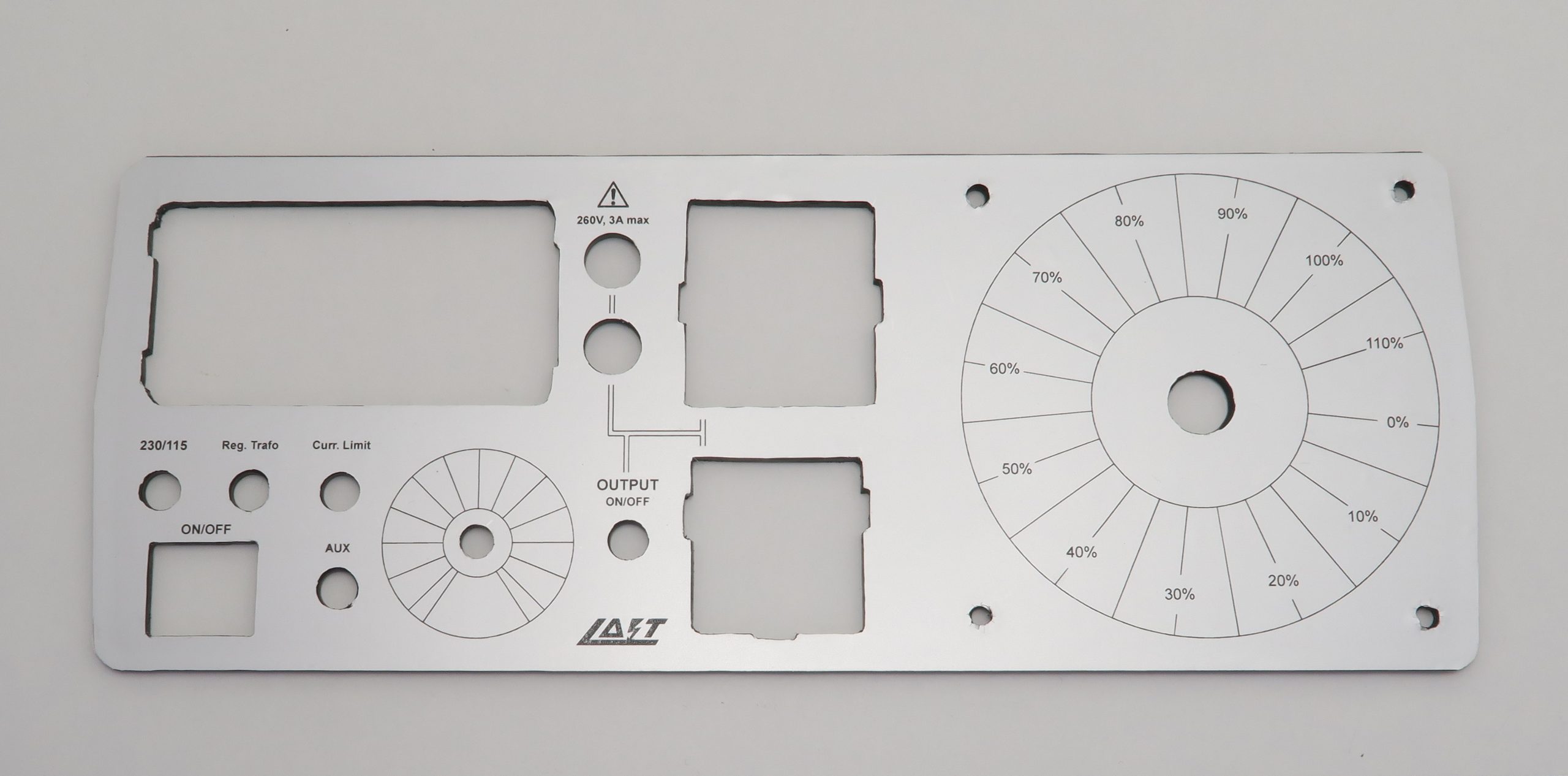
Front panel Graphis design
I designed front panel graphic and printed it on my laser printer on silver Avery Zweckform label sheet L6013-20. I am not very happy with the quality of the labels since they are very prone to even the gentlest scratches (gentle scrape of fingernail). But I don’t have anything better so it will just have to do.
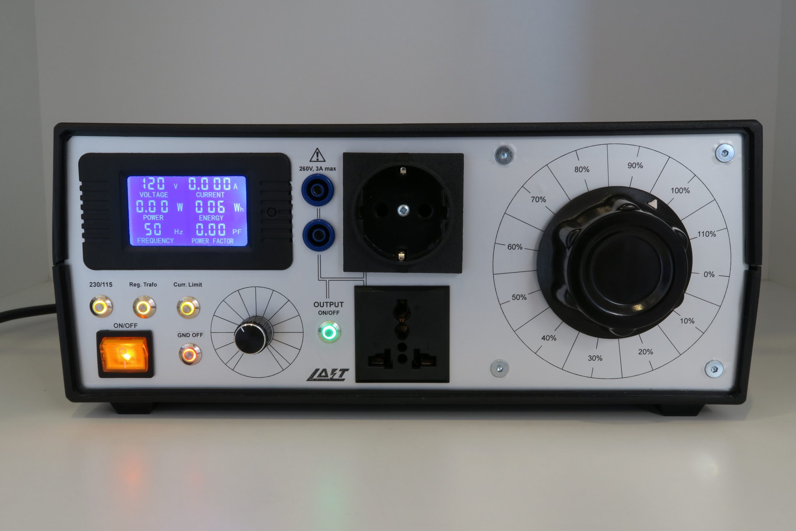
Assembled VIT

Front Panel Assembled 
Back Panel Assembled 


Working Unit
Most important thing is DUT safety!!!
That is the reason why these conditions had to be met:
- Startup conditions must not risk any unplanned power to Device Under Test.
- Default relay connections were all designed to be in Normally Open state. For example, output relay is OFF by default and DUT is disconnected from any power.
- Internal wiring was done in a way that any accidental turning ON of output, only default mains conditions can be applied (230V with earth connected).
Code:
Code was also written in a way to maximize the safety of DUT
ON Startup:
- All relays in OFF state
- Output disconnected (Main output is OFF)
Operating:
- Short press of the button enables the chosen option
- Short press of enabled option turns it off
- If Output is enabled, any change of options automatically turns it OFF
- Output needs to be turned ON after any change (safety reasons)
Current limit (Arduino interrupt)
- Current limit condition has the highest priority
- If current limit condition is true, Output is immediately turned OFF
- If current limit condition still exists Output can’t be enabled (LED warning blinking)
- Only when current limit condition is cleared Output can be re-enabled
That is basically it.
Code is crude and possibly over-complicated, but it works.
Coming up…
Softstart – (600VA transformer is not very powerful but still trips the fuse sometimes)
Video of a VIT in action
Improving current limit ability by adjusting max. range by 3A per full potentiometer turn.
Idea to be added in future:
Saving default startup options in eeprom
IMHO good ideas but not integrated in final product for various reasons:
Serial/Parallel isolation transformer configuration for maximum 115V power
AC-DC output option
Impressive! You had a lot of patience for making that nice box with manual tools. Very compact design too.
I came here thanks to an article on H@D.
You could add a layer of lacquer on the front panel to protect it from scratches. It exist in mate and satin finish if you don’t like mirror polished look. Of course you should try it out on a test piece first.
Thank you. It was kind of relaxing though 🙂
Good idea about the lacquer. I’ll give it a try on a test piece. Label I’m using is quite prone to scratches.
As I saw the last picture on hackster.io I thought – wow – well-considered and professional. I’m also impressed.
Thank you very much
It is still a quite expensive and large but nice project. Because I bought a ready working short current protected 350 Watt medical isolation transformer for just about less than 50 Euro/dollar! Your design will be expensive on just shipping cost for getting all parts alone!
Dimensions are: 30x12x22cm. It is not small, but for all the functionalities it packs I would say it is quite compact. Regarding the price, you are right, it is not cheap. Even with isolation transformer that was locally sourced the price was around 250€.
50 euro??? Where?
Hey Ho,
If you want, I could Laser Engrave it for you 😛
Alternatively CNC Mill it
I’m Based in Berlin.
Cheers
Thank you Tig3rch3n for very generous offer. But for now, I will deal with it the way it is cause I just can’t make myself to disassemble everything again 🙂
Hello,
Looking for a variac, I’ve found this page and finally, my project is a bit inspired from it.
I’m not using exactly the theme meter but the PCB is the same :
WARNING everything on this meter is NOT isolated from the INPUT; in this case, the external power is connected with the output of the variac and… with the arduino + USB port !!!!! It’s that why I’ve add an extra coil to the isolated transformer just to power the meter.
For more security, I’ve add a variac low position switch to avoid activate the output if the variac is not to the low position; Vin and Vout sens to the arduino and a warning if Vout is higher than Vin; L/ground and N/ground sensor to detect groung fault. Based on a Arduino nano every and a Nextion LCD.
Very nice project. Thank you
Cordially
Hey lereparateurdepc,
Thank you for your comment. It is a valid point. I will look in to it.
I am extremely happy if you got even a little bit inspiration from this.
That makes the whole idea of my website worth it.
All the best, Lajt
Impressive! Really professional looking panel… Inspiring layout indeed, well done cable harness. Cudos to you! found this while contemplating (at least two years now) that I have to make a similar instrument in the near future. I’m going for more power though, 2kVA. My biggest issue was to get a enclosure stirdy enough to handle a toroid at 17kg, a variac at 18 and some other bits and pieces. But found one from Hammond just a few weeks ago. I thought about using Arduino for some logic, but wen’t for a solution that does not depend on bugs in code. The soft-start, that in my case is crucial at 2kVA, is only based on electronics using a supply by itself
Thank you for your kind words.
More powerful device would also better suit my needs but bench space was the main constrictor.
Arduino is cool and all but can be buggy in some cases so I definitely support your decision.
I have issues with some transients changing my states when they shouldn’t be.
Ferite cores didn’t help so my next step is changing the pull up resistor values.
Regardless, it would be a wise choice to use latching switches to control the relays.
My soft-start solution was a 1.5 Ohm, 20W resistor being bypassed by an electronic timer after 1 second on turn ON.
Works flawlessly.
Wish you luck with your build.
Kind regards,
Lajt
I just built a similar set up with similar modifications to the AC power meter and then came across your build. https://youtu.be/E57x1yfa94Y
It looks awesome.
DC option is a nice touch.
Wow!!! That literally looks like a high end piece of equipment. Amazing to have designed every single aspect of it yourself!!!
I’m majorly impressed! You should be proud! 🥳👏🥇
Thank you for your kind words. Much appreciated.